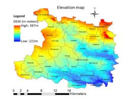
Georeferencing of Toposheet
Introduction
Georeferencing is a process of establishing a mathematical relationship between the image coordinate system and the real world spatial coordinate system.
Georeferencing an important process of spatial data including both raster and vector data. By this process of georeference, different measurement based analysis such as distance and area as well as locating object on ground can be possible on both type of spatial data.
These georeferenced data can be used for mapping and change detection analysis also for measurement distances between two given point/locations. This is possible only because of georeferencing otherwise un-georeferenced data will treat as image in which only features can be visualized and no measurements can be done.
Georeferencing is primary steps in remote sensing process for spatial data and all GIS and image processing software can be used for georeferencing.
To georeference a satellite image one need to use Ground Control Points (GCPs). GCP is a location on the earth’s surface with known coordinates on earth and Toposheets/satellite image, i.e., geographic and pixel coordinates respectively.
GROUND CONTROL POINTS
The relation between the image and the coordinate system of maps are determined by assigning map coordinates to number of points that can be located accurately on the map and identifiable in the image as well.
These points are called as ground control points or tie points.
These points are well defined and easily recognizable features that can be located accurately on a map and on the corresponding image.
To georeference mathematical model need to select in this example polynomial model selected and in this model need to define model order to execute process.
Below table shows minimum number of GCPs/Tie points required to start model. For example if model order 1 selected then minimum 3 GCPs required to start model.
|
Model Order
|
No. of GCPs required
|
|
1
|
3
|
|
2
|
6
|
|
3
|
10
|
|
4
|
15
|
|
5
|
21
|
In this article georefrencing explained using QGIS software, somehow the conceptual process is common in all software but may be only difference in tools place.
Open QGIS by clicking on Start by going to All Programs and open QGIS Desktop 3.8.3 by clicking on it.
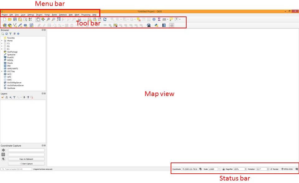
Following window will open
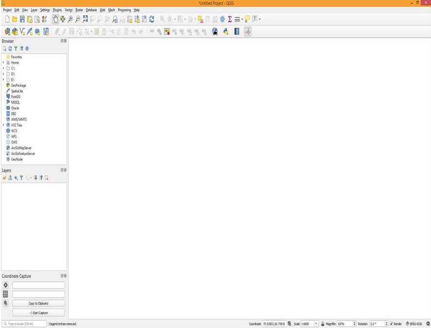
Different components of QGIS are displayed in above QGIS window such as Menu Bar, Tool Bar, QGIS browser, Map Layer, Map view and Status Bar
To start georefrencing Open Georeferencer window via Raster Georeferencer
Following window will open

Note: If Georeferencer Plugin is not there in Raster menu bar then go to Plugins
Manage and Install Plugins check box Georeferencer GDAL (follow these steps)
Step 1
Click on Plugins

Step 2
Click on Manage and Install Plugins

Step 3
check box Georeferencer GDAL

Step 4
Now Open Georeferencer window via Raster go to Georeferencer
Georeferencer window will open and this window have two parts
1. Main work space (upper part) – It displays the raster map to be georeferenced and allows user to input the geographic coordinates of control points
2. GCP Table (Lower part)- It displays the Ground control Point data and residuals.

Now you can start Georeferencing by adding the toposheet.
Add the toposheet by clicking on File and open Raster
A pop up window will open to select and open the toposheet file. After selecting the toposheets.tif file click open.
Toposheet will be loaded in the Georeferencer window
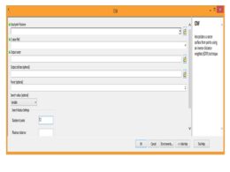
Then set the spatial reference settings for the toposheet by clicking on Settings and go to Transformation settings. Following window will open

Select the transformation type by clicking on the ‘Transformation type’ drop-down menu and select ‘Polynomial 2’ (if you want to use second order polynomial transformation). Polynomial 2 will require minimum 6 GCP’s and 1 more GCP (for check) i.e., 7 GCPs on the toposheet.

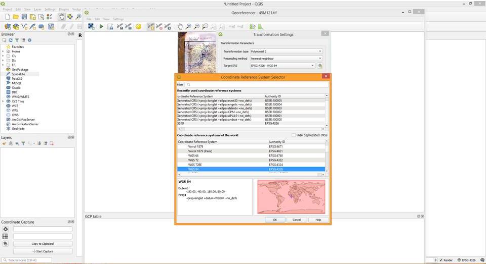
Define Coordinate Reference System in Target SRS and click on world symbol highlighted with red box.

Select the Coordinate Reference System (CRS) from the Coordinate Reference System selector window and
click OK.
Now define output file in Output raster

‘Check’ the check box ‘save GCP points’, ‘Use 0 for transparency when needed‘, and ‘Load in QGIS when done‘. Then click ‘OK‘.

Start adding GCP’s to toposheet by zooming the corner of the toposheet (use view tool for Zoom in or zoom out) and identify the intersection of the latitude and longitude. Click on Edit and Add Point

The mouse will transform into a ‘+‘ sign, which would be used to click on the center of the intersection. Enter the coordinates of the point in ‘Enter map coordinates’ window

Note: enter ‘Longitude or Easting’ in X field and ‘Latitude or Northing’ in Y field by using ‘space bar’ to separate the Degree value from Minutes value. Then click ‘OK’.

After adding all the GCP points, check the GCP table. The last column of GCP table ‘residual [pixels]‘ displays error values associated with the GCPs. An error value of 1 or less than 1 would be satisfactory.
In this georefrencing process to maintain accuracy RMS error should be low as much as possible.

Note: if mean error is greater than 1, then adjust the GCP points using Move GCP point button or Delete point button.
After adjusting the mean error around or below 1, click the ‘Start Georeferencing‘ Button. The processing will start and after processing you will get the georeferenced image.